
 English
 Русский
 Español
 Français
 Deutsch
 简体中文
 Árabe
 Português
 日本語
 한국어
 हिंदी
 Prancis
 Türkçe
 Tiếng Việt
 Italiano
 ไทย

U-Shaped Silicon Carbide Rods for Industrial Heating Applications
U-Shaped Silicon Carbide Rods for Industrial Heating Applications
U-shaped silicon carbide rods are used in industrial furnaces where the installation space, electrical connection position, or heating chamber design requires a specific element shape. Their two legs connect through a curved bridge, allowing both electrical terminals to be located on the same side of the furnace.
The right U-shaped silicon carbide rod must match the furnace dimensions, required heating output, and electrical supply. Buyers should check the hot zone, cold ends, rod diameter, center distance, and operating conditions before ordering a replacement or custom element.
Why U-Shaped Silicon Carbide Rods Are Used in Industrial Furnaces
A U-shaped silicon carbide rod can be useful when a straight heating element cannot span the required heating area or when both electrical connections need to remain on one side of the furnace. This layout can simplify installation in certain furnace designs.
The hot zone generates most of the heat, while the cold ends provide the electrical connection areas. The bridge joins the two legs. Each section must be designed for its intended role and operating temperature [1].
U-shaped SiC rods may be used in ceramic kilns, glass furnaces, heat-treatment equipment, and other high-temperature applications. The suitable element type depends on the furnace design and the required operating conditions. A U-shaped element is not automatically more energy-efficient than a straight rod; its main advantage is that its geometry can suit particular installation requirements.
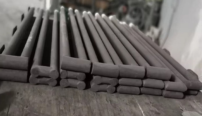
How a U Type Silicon Carbide Rod Works
A U type silicon carbide rod generates heat when electric current passes through its resistive hot zone. Electrical energy is converted into heat, which is transferred to the furnace chamber and the materials being processed.
The hot zone and cold ends have different electrical and thermal functions. Their dimensions and resistance characteristics affect how heat is distributed along the element. Research on SiC heating elements also shows that electrical resistivity changes with temperature and can increase during long-term operation [2][3].
The power supply must therefore suit the element's electrical specifications. Voltage, current, resistance, and power-control range should be checked together rather than selected independently. The element manufacturer's rated values should be used for electrical design and commissioning.
U-Shaped Silicon Carbide Rods vs. Straight SiC Heating Rods
Both U-shaped and straight silicon carbide rods provide resistance heating. The main difference is their geometry and the way they connect to the furnace.
| Feature | U-shaped SiC rod | Straight SiC rod |
|---|---|---|
| Element shape | Two legs joined by a bridge | One straight heating element |
| Terminal position | Both terminals can be on one side | Usually located at opposite ends, depending on design |
| Installation | Suitable for specific single-sided access or drop-through layouts | Suitable where the furnace supports a straight element |
| Key dimensions | Hot-zone length, cold-end length, diameter, center distance, overall length | Hot-zone length, cold-end length, diameter, overall length |
| Main selection concern | Bridge clearance and spacing between the two legs | Element span and support arrangement |
The best option depends on furnace access, available space, heating-zone layout, and electrical design. The element shape should be selected to fit the furnace rather than assuming one design performs better in every application.
Key Factors That Affect U-Shaped SiC Rod Performance
Several operating factors influence the service life and performance of silicon carbide heating elements.
Resistance aging: SiC elements can gradually increase in resistance during use. Research identifies oxidation and changes in material properties as important factors in this behavior [2][3]. Rising resistance may change the power available from the existing electrical supply.
Operating temperature and atmosphere: The furnace temperature, surrounding gases, and materials being processed affect element behavior. The permissible operating range must be confirmed for the specific SiC grade and atmosphere.
Electrical loading: The power applied to the element affects its temperature distribution. Incorrect electrical matching or unsuitable control settings can cause excessive loading and shorten service life.
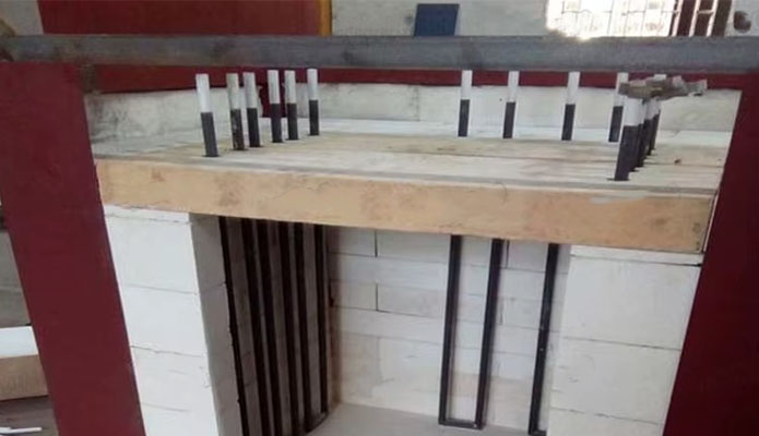
Installation stress: SiC is a ceramic material and can fracture if subjected to unsuitable mechanical loads. The mounting arrangement should allow for the element and furnace to expand during heating. The U-shaped bridge also needs appropriate clearance and support for the specified mounting position [1].
Common Problems with U-Shaped Silicon Carbide Heating Rods
A rod that does not match the furnace dimensions may be difficult to install or may place unwanted stress on the bridge and legs. Incorrect hot-zone positioning can also produce uneven heating.
Electrical problems may occur when replacement elements have unsuitable resistance values or are not matched to the existing circuit. As SiC elements age, the furnace may heat more slowly or require changes to its power settings. Resistance and operating records can help maintenance teams identify changes before replacing elements [2][3].
Other potential issues include loose electrical connections, insufficient clearance, and cold ends exposed to temperatures beyond their design limits. The cause should be checked before changing the element type or increasing the power supply.
When to Choose a Custom U-Shaped Silicon Carbide Rod
A custom U-shaped silicon carbide rod is worth considering when standard dimensions do not fit the furnace or when the existing element needs a specific terminal arrangement.
Custom design may be required for a different heating-zone length, cold-end length, rod diameter, bridge size, or distance between the two legs. The design should also account for the furnace opening, mounting position, and electrical requirements.
Before production, confirm the complete dimensions and electrical specifications. A drawing is especially useful when the element must replace an existing rod or fit a restricted installation space.
What to Check Before Ordering Custom U-Shaped SiC Rods
Before placing an order, prepare the following information:
Heating-zone length: The length required inside the active furnace area.
Cold-end length: The length needed for the connection and mounting arrangement.
Rod diameter: The diameter specified for the element and furnace design.
Center distance: The distance between the two legs of the U-shaped rod.
Overall length and bridge dimensions: Confirm that the element fits the furnace opening and available clearance.
Electrical specifications: Provide the required voltage, resistance, power, and connection arrangement.
Operating conditions: State the furnace temperature, atmosphere, heating cycle, and installation position.
A dimensioned drawing or a clear sketch can help confirm these details before production. The final specification should be reviewed against the furnace design and the heating element manufacturer's technical data.
Choosing a suitable U-shaped silicon carbide rod starts with accurate dimensions and a clear understanding of the furnace's operating conditions. Correct electrical matching, suitable installation, and regular resistance checks can help support stable furnace operation.
References
[1] Silcarb. U-Shaped Alpha SiC Rods — Technical Information.
https://silcarb.com/sic-elements/u-shaped-alpha-sic-rods.php
[2] Silicon Carbide Heating Elements. Ceramics International, Volume 24, Issue 5, 1998, pp. 371–377.
https://doi.org/10.1016/S0272-8842(97)00024-2
[3]Chun, T., Kim, S., Chung, J., and Lee, H. Numerical Study on Temperature and Thermal Stress Behaviors in Silicon Carbide Heating Elements Within High-Temperature Annealing Furnaces. Applied Thermal Engineering, 2025, 260, 125047.
https://doi.org/10.1016/j.applthermaleng.2024.125047
Online Message
RELATED PRODUCTS

LAR's W type silicon carbide rod is a high-efficiency electric heating element designed for three-phase power systems. This w type silicon carbide rod integrates multiple heating sections into one structure. Many furnaces use silicon carbide three-phase rod designs to achieve balanced electrical load and stable heating performance. Manufacturers produce w type silicon carbide rod products using high-purity silicon carbide materials. The production process includes recrystallization at high temperature. The structure ensures that each silicon carbide three-phase rod delivers consistent resistance and thermal output. LAR's A 3 phase single silicon carbide rod combines three heating legs into one unit. This design reduces installation complexity and improves space utilization. Many industrial systems prefer w type silicon carbide rod solutions because the structure supports uniform heat distribution. Industries such as ceramics, metallurgy, and glass widely use silicon carbide three-phase rod products. These systems rely on 3 phase single silicon carbide rod designs to maintain stable temperature and efficient energy use.
LAR's Oxide-bonded SiC products are refractory components made from silicon carbide grains bonded with oxide phases. These oxide-bonded SiC products offer a balance between cost and performance. Many industries select oxide bonded silicon carbide materials for high-temperature structural applications. Manufacturers produce oxide-bonded SiC products by mixing silicon carbide with oxide binders such as silica or alumina. The process forms a strong ceramic matrix after high-temperature firing. The structure allows oxide bonded silicon carbide components to maintain stability under thermal load. LAR's Oxide-bonded SiC products show good oxidation resistance and moderate thermal conductivity. These oxide bonded silicon carbide materials perform well in oxidizing kiln atmospheres. Many users choose oxide-bonded SiC products for kiln furniture and heat-resistant supports. Industries such as ceramics and metallurgy widely use oxide bonded silicon carbide components. These oxide-bonded SiC products support stable firing conditions and improve production efficiency.
LAR's silicon nitride igniter rod is a high-performance heating component used for ignition in industrial and domestic burner systems. This silicon nitride igniter rod converts electrical energy into heat and enables rapid ignition. Many systems rely on silicon nitride igniter rod products to achieve stable and efficient startup. Manufacturers produce silicon nitride igniter rod components using advanced ceramic processing and metallization technology. The structure combines a dense ceramic body with an internal heating element. A si3N4 ceramic ignitor rod provides excellent thermal efficiency and reliable ignition performance. LAR's Nitride bonded silicon carbide is another material used in high-temperature environments. Nitride bonded silicon carbide offers good thermal shock resistance and mechanical strength. However, silicon nitride igniter rod products provide faster heating response and better oxidation resistance compared with nitride bonded silicon carbide components. LAR's silicon nitride igniter rod products operate in gas burners, oil burners, and pellet stoves. Many users select si3N4 ceramic ignitor rod solutions to improve ignition reliability and reduce energy consumption.
LAR's Gun-shaped silicon carbide rod is a specialized electric heating element used in high-temperature industrial furnaces. This gun-shaped silicon carbide rod features a unique structure with a cold end and a hot zone. Many heating systems use gun type silicon carbide rod designs to achieve efficient and controlled heating. Manufacturers produce gun-shaped silicon carbide rod products using high-purity silicon carbide materials. The process includes recrystallization or reaction bonding. A professional gun-shaped silicon carbide rod factory ensures stable electrical performance and precise dimensions. LAR's Gun-shaped silicon carbide rod provides uniform heat generation and high thermal efficiency. The structure allows easy installation from one side of the furnace. Many users choose gun type silicon carbide rod solutions because the design simplifies maintenance and replacement. Industries such as ceramics, metallurgy, and glass widely use gun-shaped silicon carbide rod products. A reliable gun-shaped silicon carbide rod factory supplies consistent quality for continuous high-temperature operation.
LAR's H-shaped silicon carbide rod is a high-efficiency electric heating element used in industrial furnaces. This h-shaped silicon carbide rod features a double-leg structure connected by a heating bridge. Many heating systems adopt h type silicon carbide rod designs to improve thermal uniformity and electrical performance. Manufacturers produce h-shaped silicon carbide rod products using high-purity silicon carbide materials. The process includes high-temperature recrystallization to form a dense structure. Each h type silicon carbide rod provides stable resistance and consistent heat output during operation. Custom LAR's h-shaped silicon carbide rod solutions allow flexible design based on furnace layout. Many users select custom h-shaped silicon carbide rod products because the structure improves installation efficiency and space utilization. Industries such as ceramics and metallurgy widely use h-shaped silicon carbide rod products for high-temperature heating applications.
LAR’s Db-type silicon carbide rod is a high-efficiency electric heating element designed for industrial furnaces. This db-type silicon carbide rod features a double-bent structure that increases the effective heating length within limited furnace space. Many industries select db-type silicon carbide rod products to improve thermal efficiency and optimize furnace layout. Manufacturers produce db-shaped silicon carbide rod products using high-purity silicon carbide materials and recrystallization technology. The process forms a dense and stable structure. A professional db-type silicon carbide rod factory manages each production stage to ensure consistent resistance and reliable performance. LAR’s Db-shaped silicon carbide rod includes two heating sections connected by a curved bridge. This structure allows the db-type silicon carbide rod to deliver higher power output compared to straight rods. Many furnace engineers prefer db-type silicon carbide rod designs because they reduce installation space while maintaining strong heating capacity. LAR’s Db-type silicon carbide rod operates in oxidizing atmospheres. The surface forms a protective silica layer at high temperature. This layer helps the db-shaped silicon carbide rod resist oxidation and extend service life. Many users depend on an experienced db-type silicon carbide rod factory to ensure long-term stability.
LAR’s Slot-type silicon carbide rod is a specialized electric heating element designed for high-temperature industrial furnaces. This slot-type silicon carbide rod features a longitudinal slot structure that increases surface area and improves heat distribution. Many industries select slot-type silicon carbide rod products to achieve faster heating response and better temperature uniformity. Manufacturers produce slot-type silicon carbide rod using high-purity silicon carbide and recrystallization technology. The process creates a stable and porous structure that supports efficient heat radiation. A professional slot-type silicon carbide rod supplier controls production parameters to ensure consistent resistance and reliable performance. Custom slot-type silicon carbide rod is widely used in applications that require precise heating control. The slot design allows better airflow and heat exchange inside the furnace chamber. Many furnace designers prefer custom slot-type silicon carbide rod solutions to meet specific thermal requirements. LAR’s Slot-type silicon carbide rod operates in oxidizing atmospheres. The surface forms a protective silicon dioxide layer at high temperature. This layer helps the slot-type silicon carbide rod resist oxidation and maintain long-term stability. Many users rely on an experienced slot-type silicon carbide rod supplier to ensure dependable operation.
LAR’s U-shaped silicon carbide rod is a commonly used electric heating element for industrial furnaces. This u-shaped silicon carbide rod features a U configuration that connects two parallel heating sections. Many industries select u-shaped silicon carbide rod products to simplify wiring and improve installation efficiency. Manufacturers produce u type silicon carbide rod using high-purity silicon carbide and recrystallization processes. The material forms a strong and stable ceramic structure. This structure allows the u-shaped silicon carbide rod to operate reliably at high temperatures. Many furnace systems rely on u type silicon carbide rod designs for consistent heating performance. Custom u-shaped silicon carbide rod is suitable for furnaces with limited installation space. The U design reduces the number of terminal connections. This feature helps operators install and maintain the heating system more easily. Many engineers choose custom u-shaped silicon carbide rod solutions for compact furnace layouts. LAR’s U-shaped silicon carbide rod operates in oxidizing atmospheres. The surface develops a silicon dioxide protective layer at high temperature. This layer helps the u-shaped silicon carbide rod resist oxidation and extend service life. Many users depend on stable u type silicon carbide rod products for long-term furnace operation.
LAR’s silicon carbide heating rods are high-performance ceramic heating elements widely used in industrial furnaces and high-temperature equipment. These silicon carbide heating rods provide stable and efficient heat generation, ensuring uniform temperature distribution. Many industries rely on silicon carbide heating rods to maintain product quality and operational efficiency. Manufacturers produce silicon carbide heating rods using precision forming and sintering technology. A professional silicon carbide heating rod factory ensures that each silicon carbide sic rod heater meets strict quality and dimensional standards. LAR’s silicon carbide heating rods feature excellent thermal conductivity and strong resistance to chemical corrosion. They are suitable for long-term use in furnaces, kilns, and heating chambers. The dense ceramic structure of each silicon carbide heating rod ensures durability and reduces the risk of breakage under high temperatures. LAR’s silicon carbide sic rod heaters perform well in molten metal, ceramic, and glass processing environments. Many users choose a reliable silicon carbide heating rod factory to guarantee consistent performance and long service life.
